Mon–Fri 9:00–18:00 · CST (UTC+8) · Shandong, China
Product Family

Power Electronics Busbars

9 engineered models in this family — every one fully custom.
Models

Power Electronics Busbars

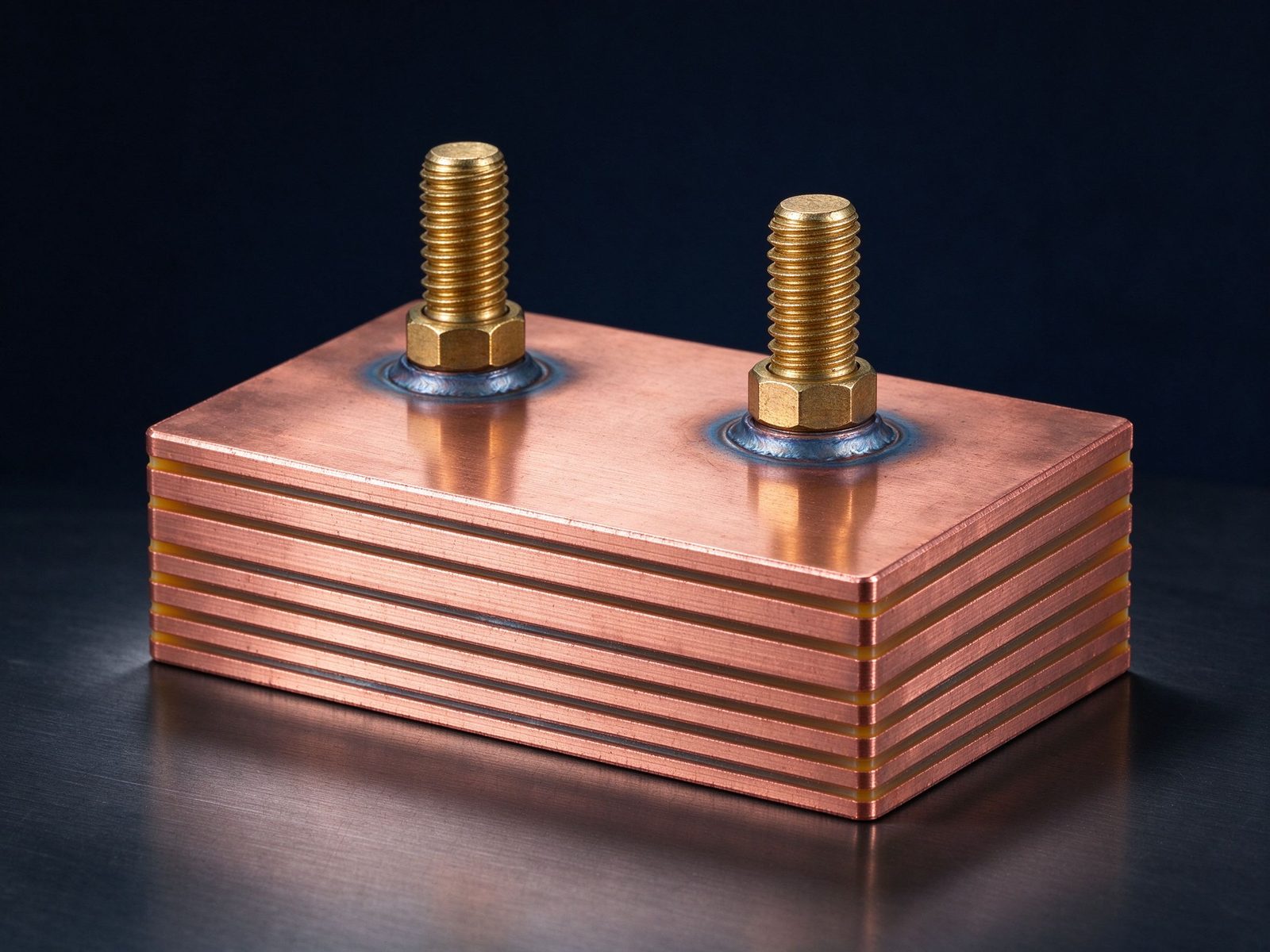
Welded Busbar Assembly

Welded Busbar Assembly

Welded laminated busbar assembly for high-current power distribution with pre-mounted tabs
SY-PE-214
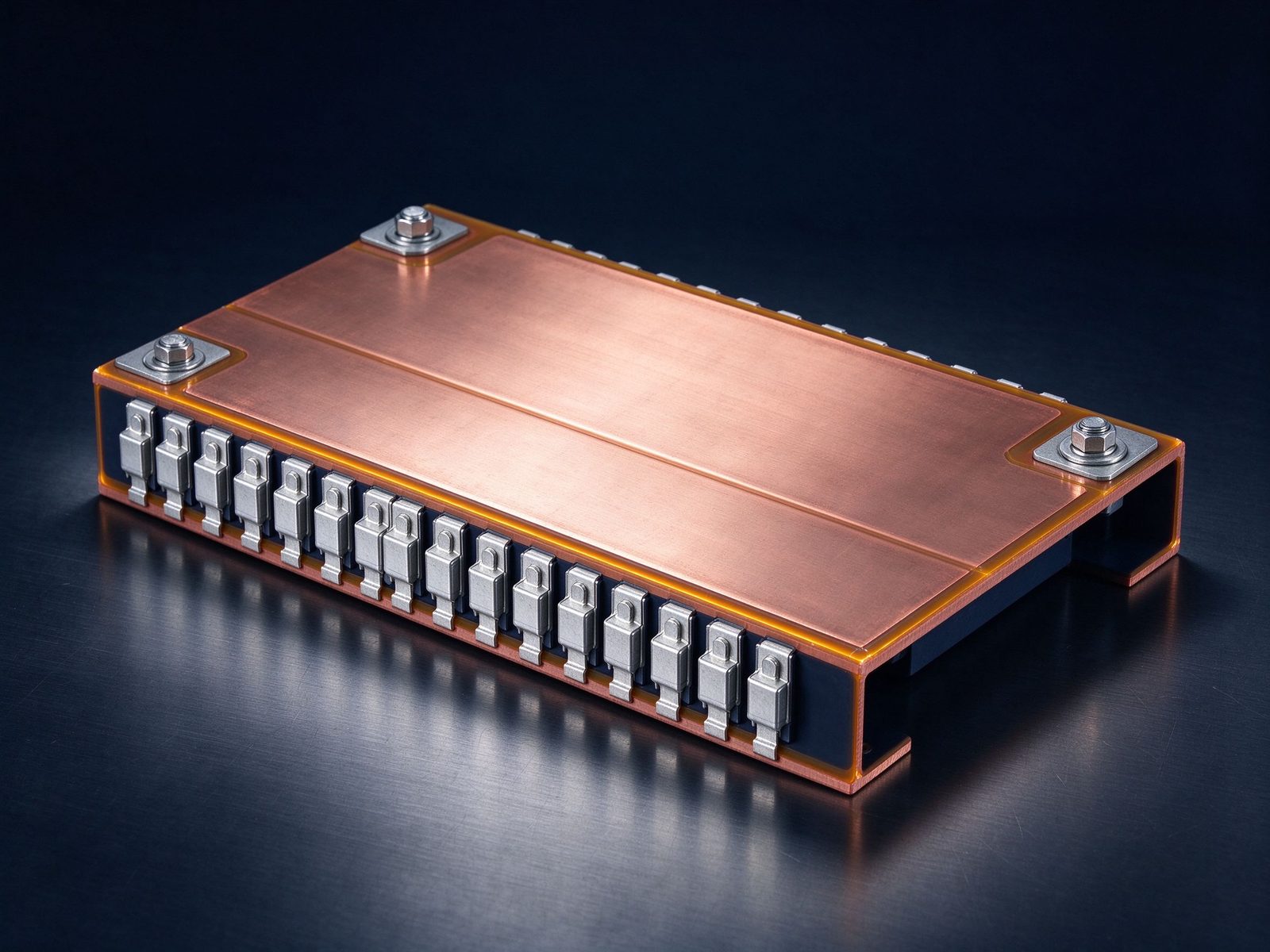
EV Inverter Laminated Busbar

EV Inverter Laminated Busbar

Laminated busbar for EV traction inverters with blade terminals for high-voltage architect
SY-PE-213
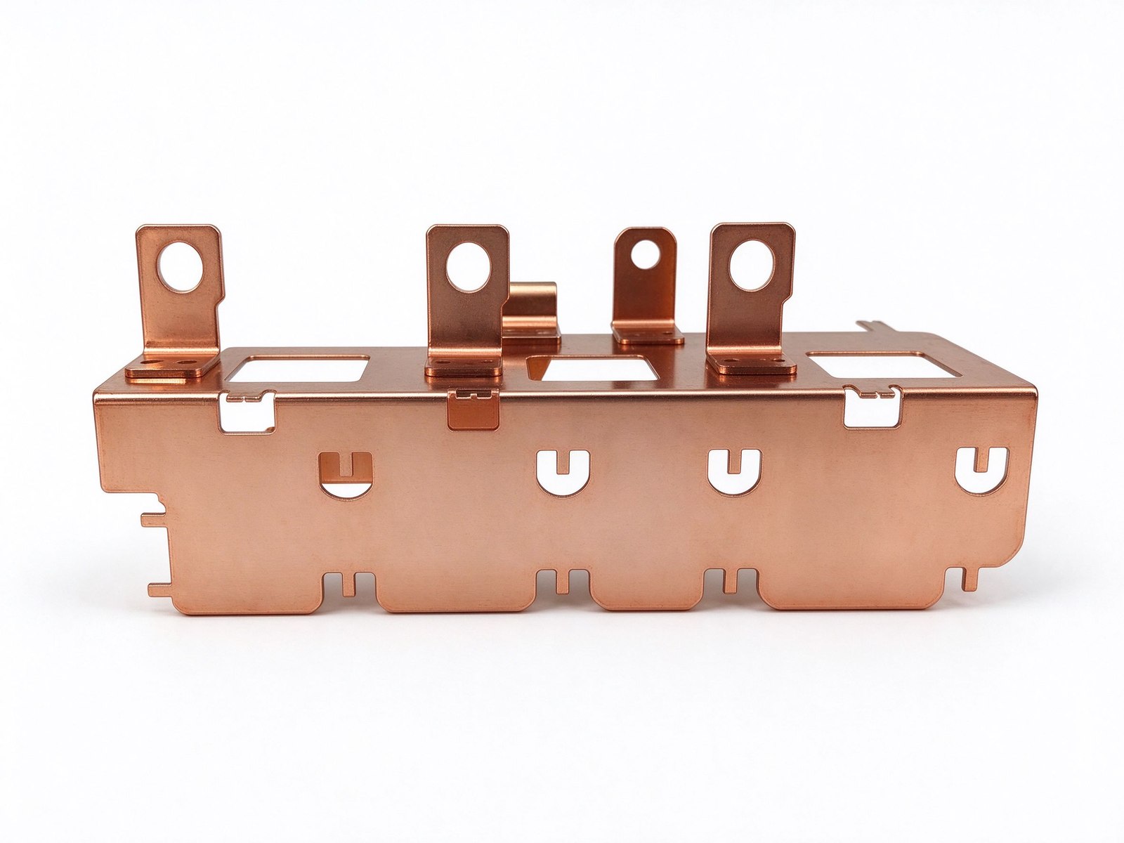
Capacitor Bank Busbar

Capacitor Bank Busbar

Multi-tab laminated busbar for capacitor bank connections in power converters.
SY-PE-212
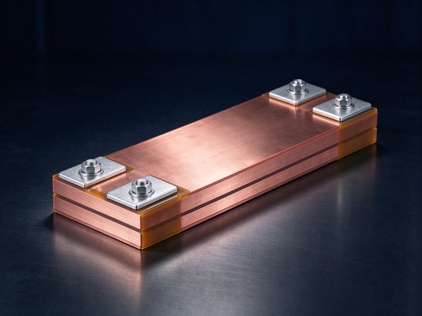
Inverter DC Link Busbar

Inverter DC Link Busbar

Long laminated DC link busbar with blade terminals for low-inductance inverter designs.
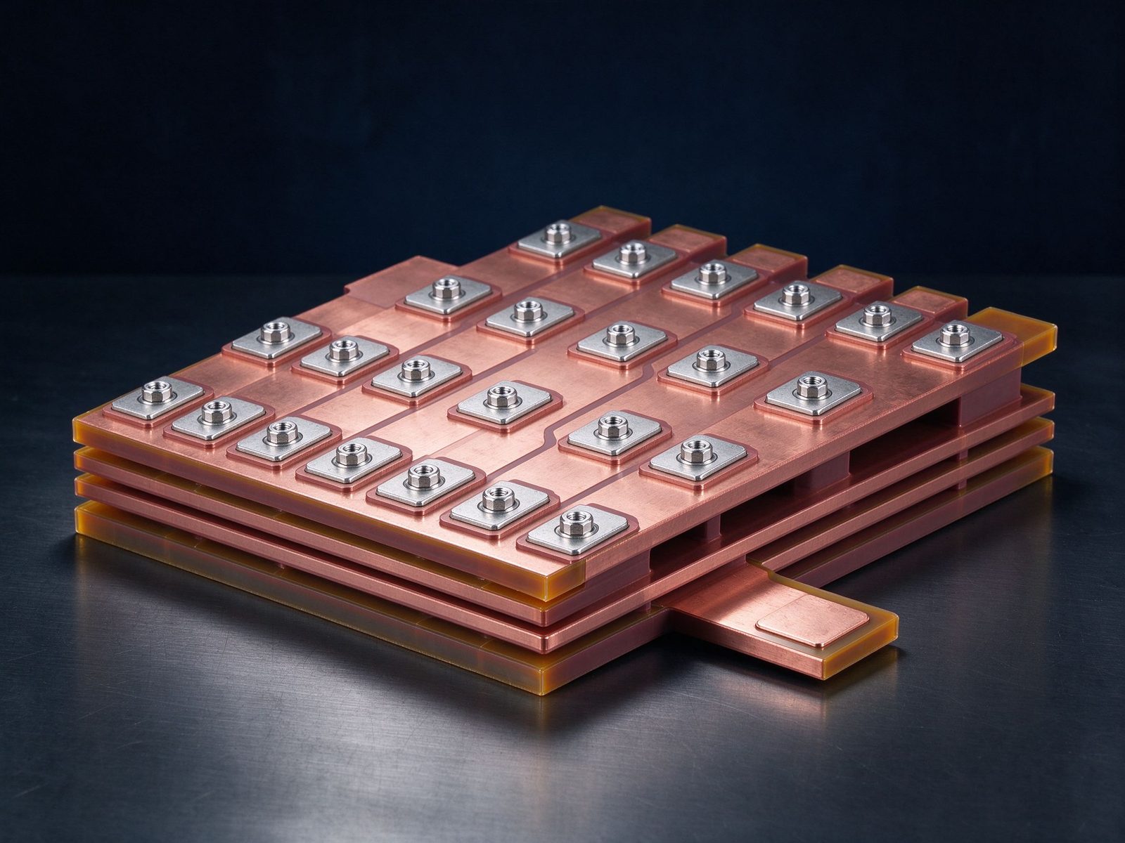
SY-PE-211
IGBT Module Busbar Set

IGBT Module Busbar Set

Laminated busbar set for IGBT power modules with matched tab terminals for phase legs.
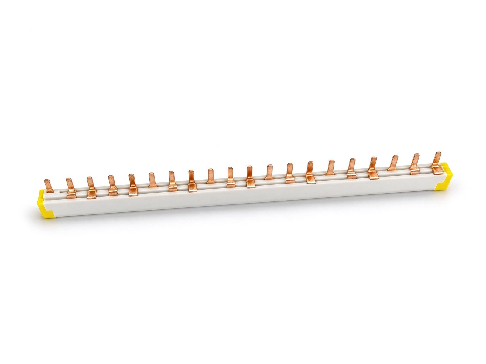
SY-PE-209
Blade Terminal Busbar Assembly

Blade Terminal Busbar Assembly

Compact laminated busbar assembly with blade terminals for low-profile power distribution.
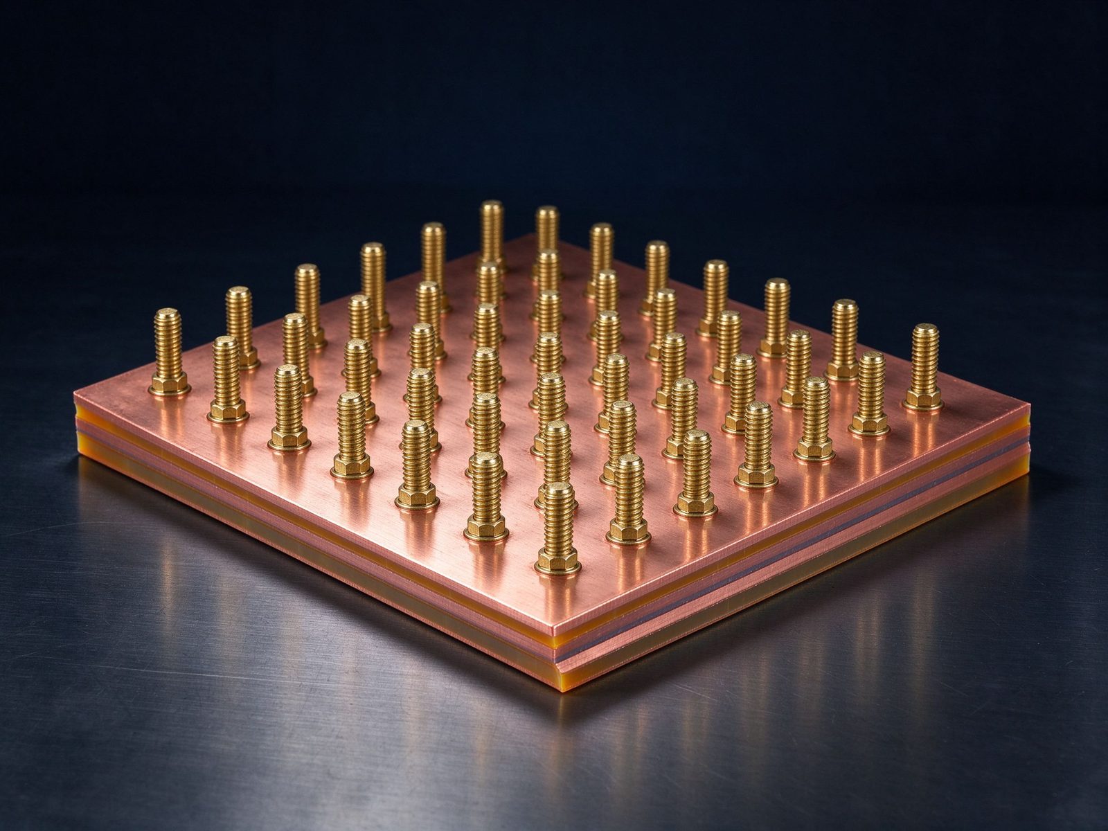
SY-PE-206
Power Electronics Laminated Busbar

Power Electronics Laminated Busbar

Laminated busbar for power converters with side tab terminals and central mounting stud.
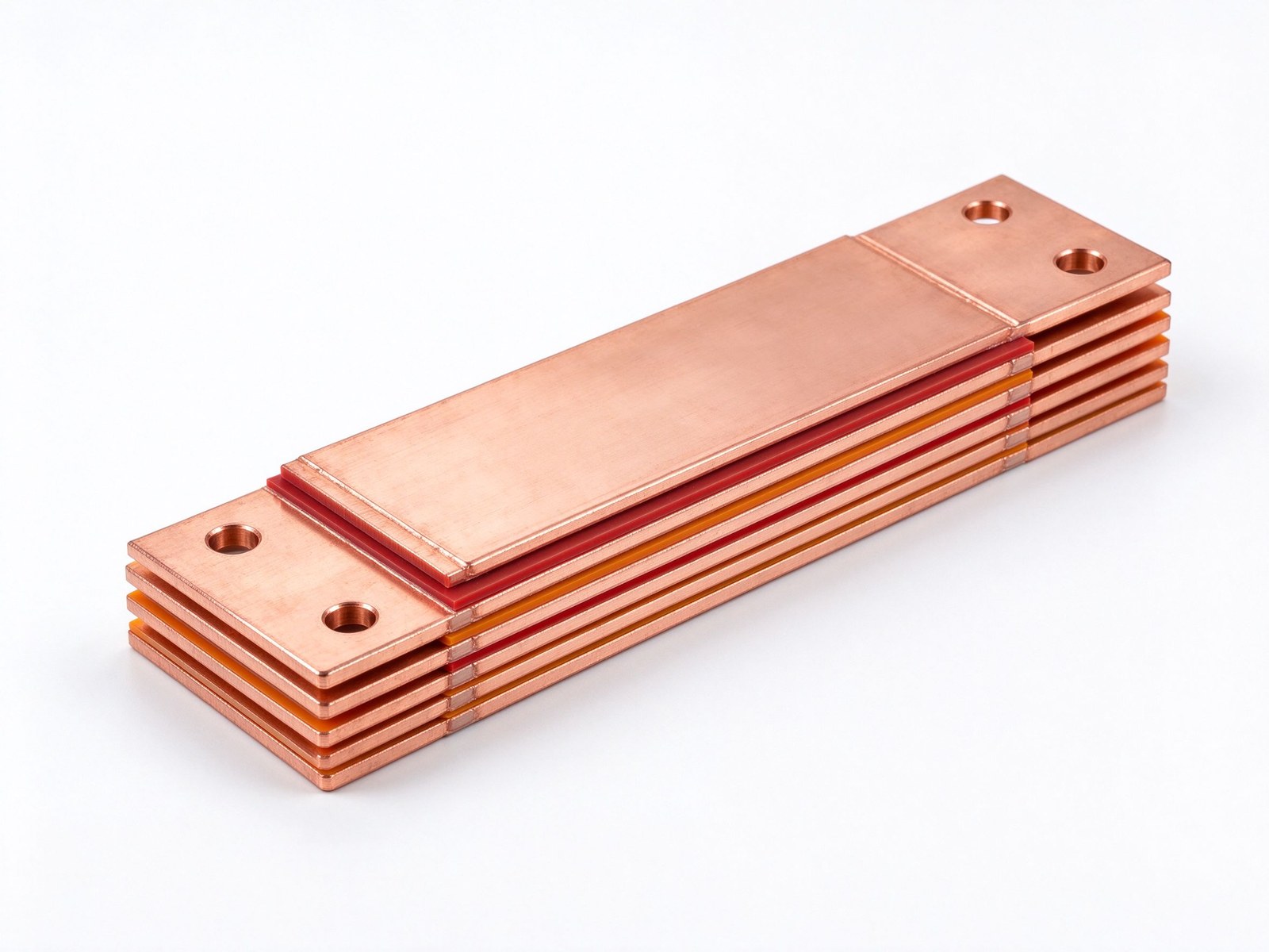
SY-PE-205
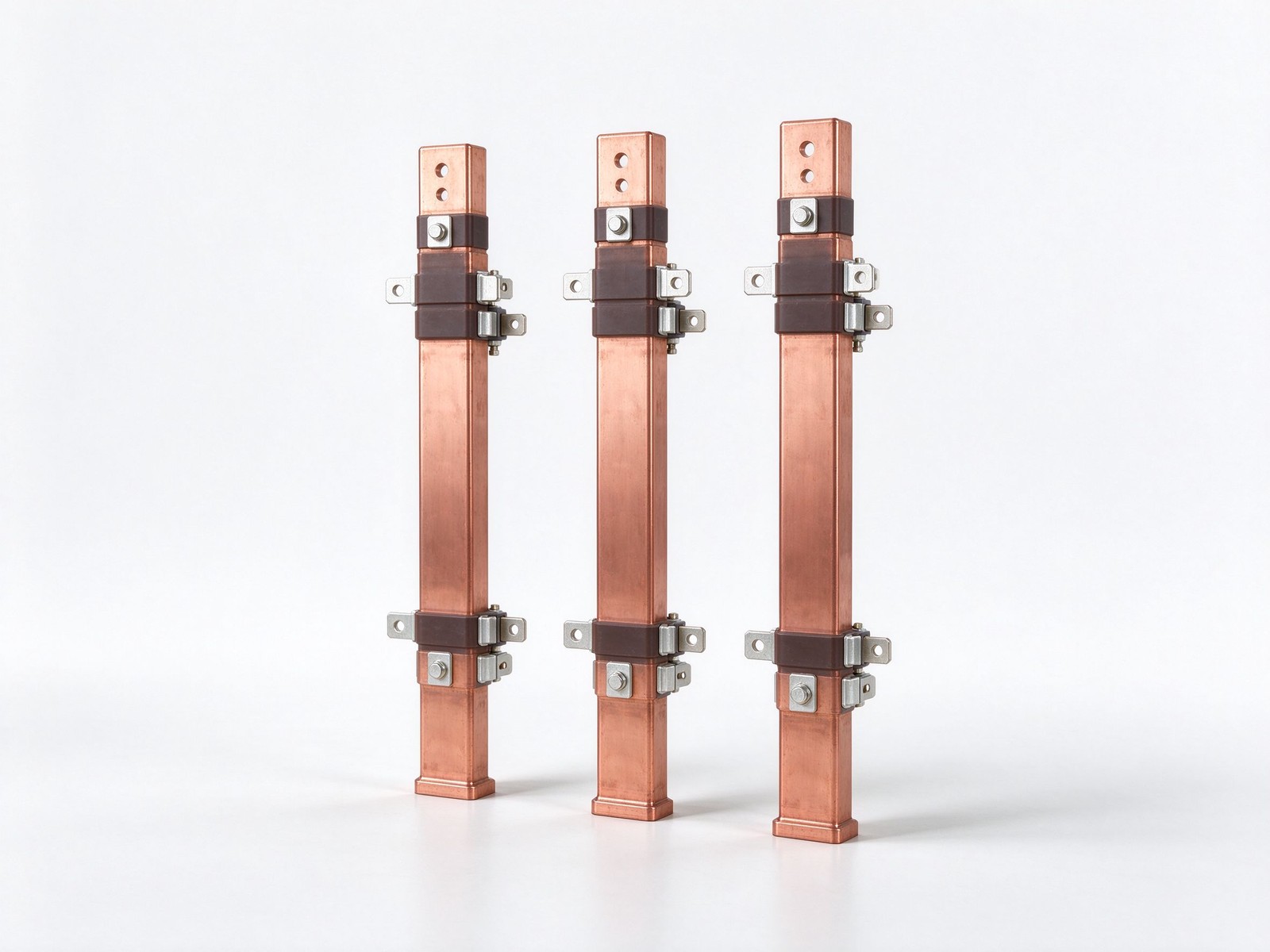
Laminated Copper Busbar

Laminated Copper Busbar

Hot-pressed multi-layer copper sandwich that cancels stray inductance for IGBT and SiC pow
SY-PE-215
LV Switchgear Busbar

LV Switchgear Busbar

Custom LV switchgear busbar routed to NEC-compliant panels, retrofits and CT/PT installati

SY-PE-216
Capabilities

What we can build

CapabilityRange
Conductor layers1–6+ (custom stack-ups)
Conductor materialC11000 copper (standard), aluminum on request
PlatingTin (standard)
DielectricsPET, Nomex, epoxy (DLF)
Terminal typesM6/M8 threaded studs, blade tabs, screw terminals, welded tabs, fused links
Current ratingPer design, up to ~1000 A
MountingIntegrated brackets, standoffs, edge seals
Incoming Materials

What goes into the stack

MaterialStandard options
ConductorsC11000 copper as standard; aluminum available on request
DielectricsPET, Nomex and epoxy (DLF) films, selected by voltage class and operating temperature
PlatingTin finish for corrosion protection and joint solderability
Explore

Where power electronics busbars earn their place

Power electronics busbars sit inside the commutation loop — between DC-link capacitors and switching modules — where every nanohenry of stray inductance counts. Three reference markets:

Solar & Wind Converters

DC links and phase legs for renewable inverters rated toward 1500 VDC, with partial discharge controlled by layout and dielectric choice.

Industrial Motor Drives

Low-inductance links from DC bus capacitors to IGBT stacks in VFDs, holding switching losses and voltage overshoot in check.

Data Center Power

Low-profile distribution laminates feeding rectifiers and server cabinets, with controlled impedance and no wiring errors.

Typical Configurations & Selection Points

Configuring power electronics busbars

Face-to-face conductor layout

DC links are built with adjacent positive and negative planes to cancel loop inductance; the dielectric thickness between them is the main lever. Capacitor-to-module geometry is locked at DFM before any tooling is cut.

Tab pitch matched to the module

Blade and screw terminals are positioned to the exact pitch of your IGBT or SiC module pins, with weld zones sized for vibration life. Send the module part number and we align the tab pattern to it.

Dielectric by bus voltage

400 V class designs standard on PET; 800 V and higher move to Nomex or epoxy (DLF) with wider edge sealing. Read the low-inductance busbar design rules before release, and see inverter DC links for reference circuits.

Project Flow

How a custom project runs

From spec review to shipped, tested parts — one accountable supplier.

Spec ReviewDrawing, current rating, layers and terminals confirmed with you
DFM ReviewEdge distances, weld zones and clearances checked before tooling
QuotationTechnical and commercial quote within one business day
Sample BuildPrototypes for fit and electrical verification
Tooled ProductionControlled process with documented QC per lot
DeliveryPacked to your requirements, test records on request
Documented Quality

Every lot tested, every lot recorded

Hipot, insulation, dimensional, visual and continuity checks per lot — with dimensional and electrical test records maintained and supplied with your shipment on request.

DFM review before toolingIn-house QC per production lotBatch test records on requestCoC / PPAP-style documentation
Engineering Resources

Go deeper

Laminated Busbar Design Guide

Construction, dielectric selection and current capacity basics.

Read the busbar design guide

Busbar Ampacity Chart

Copper current ratings with derating guidance.

View the copper ampacity chart

Busbar vs Cable

Where laminated wins — and where it does not.

Compare busbar vs cable
FAQ

Frequently asked questions

Straight answers from the engineering team.

What information do you need to quote a laminated busbar?
A drawing (PDF or DXF) or a photo of an existing sample, the required current rating and voltage class, number of conductor layers, terminal types, estimated annual quantity, and the application. With a complete specification, our engineering team typically responds within one business day.
How many conductor layers can you build?
We build custom stack-ups from 1 to 6+ layers. Layer count, terminal layout and mounting configuration are all defined by your drawing and reviewed at DFM before tooling.
Do you support low-volume prototypes before production?
Yes. Custom projects typically run: spec review, DFM, quotation, sample build for fit and electrical verification, then tooled production with documented QC per lot.
What is your typical lead time for production orders?
Sample builds ship within 5–7 working days. Tooled production runs are typically 2–3 weeks after sample approval, depending on quantity and stack complexity. We confirm a firm date with every quotation.
What is the minimum order quantity (MOQ)?
There is no MOQ for samples and pre-production prototypes. For tooled production we work with your demand — from low-volume pilot runs to series orders — so quantity is agreed per project rather than forced by a fixed minimum.
Which file formats do you accept for drawings?
We accept PDF, DXF and STEP files, plus photos of existing parts. 2D drawings with dimensions and tolerances are sufficient for quotation; a 3D model speeds up the DFM review and tooling preparation.

Designing forPower Electronics Busbars?

Send the current profile and terminal types — we will recommend a configuration from this family or quote a custom part.
